
My previous article "Valve Controlled Startup of Desalination Plant" described a moderately brutal mode of plant start-up. It does not guarantee the smooth pressure rise of the RO membranes feed but at least extends the start-up time above 5 seconds - the time taken by the high-pressure pump motor to reach a normal speed at the DOL start-up.
This article explains the principles of an intelligent start-up providing high-precision control of the RO feed pressure rise and drop.
In desalination, the feed pressure rise is associated with three phenomena: the RO feed temperature decrease, the membrane fouling increase, and the CCRO desalination - closed circuit reverse osmosis desalination method patented by Prof. Avi Efraty.
 CCRO is a batch process showing unmatched performance at low water salinity and low osmotic pressure respectively. At high salinities CCRO loses its advantages, its useful application range is limited by a maximum osmotic pressure of about 24 Barg. As seawater osmotic pressure is over 28 Barg, CCRO is not used in seawater desalination plants.
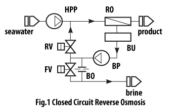
CCRO is our starting point. It is not trivial: numerous articles published since the patent granting (US7695614B2, 2008) skip the practical details of the CCRO implementation needed to solve our task. My interpretation of CCRO operation is captured by the schematic diagram shown in Fig.1.
During the RO cycle, no brine flow exits the RO membrane array. It is recirculated with a BP pump, the RV valve being open and the FV valve closed. The decrease in the volume of the recirculated feed is compensated by the HPP pump adding fresh feed water. A very small amount of feed is constantly bleeding through the BO orifice. At the maximum feed pressure, the HPP pump is stopped and the pressure inside the circuit smoothly coasts down to that of the brine-out line due to the orifice BO. During this transition, the reverse osmosis in membranes changes its direction, and the membrane cleaning starts. This bonus point is often overlooked by the CCRO opponents.
Next, the RV valve is closed, the FV is opened, and the circuit flushing - the brine replacement with fresh feed - starts. After flushing the RV is opened, and FV is closed, and the desalination at the constant rise of the feed pressure starts again.
The pressure rise speed (PRS) in the closed circuit is defined by the ratio of the pump volumetric capacity and the circuit water volume. High PRS leads to accelerated cyclic fatigue, low PRS increases the cost of the plant. To control PRS the inventors of CCRO created the buffer volume inside the membrane housing. Usually, it is within 25 - 50% of the housing volume.
How may the described mode of PRS control be applied to seawater desalination? Its principle flow diagram shown in Fig.2 includes the feed pump HPP, the energy recovery device ERD, and the booster pump BP installed at the ERD high-pressure feed discharge.
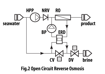 During normal operation, both pumps feed the RO membranes, with ERD pumping the feed to BP and recuperating the pressure energy of discharged brine flow.
To execute the start-up procedure the CV and DV valves are added at the ERD low-pressure end. The DV valve is installed at the ERD brine outlet line. The CV valve connects the ERD brine outlet with its feed inlet. During normal operation described above CV is closed and DV is open.
To create the closed circuit with PRS control needed for start-up CV is opened and DV is closed. The mentioned circuit includes ERD, BP, RO, and CV.
The trajectory of the feed pressure rise crosses two distinct areas of control separated by the seawater osmotic pressure (SOP).
When closed circuit pressure is below SOP, PRS is controlled by the difference between the pump energy input and the energy dissipated in the CV valve.
When the circuit pressure is above SOP, the reverse osmosis starts. It leads to fluid salinity and SOP rise and decrease in the high-pressure fluid flow rate to ERD and recuperated power respectively. To continue the process the BP pump shall compensate for the power loss and driving pressure difference in membranes. It may be done by increasing the pump rotation speed.
Here the fluid stream imbalance (equal to the RO recovery) in ERD and the pump motor size are limiting factors of PRS. In the case of the energy recovery device from Energy Recovery (PX Q300), the maximum imbalance may be conservatively set at 5%.
Below is the performance prediction at the constant imbalance of 3% of the RO system equipped with Flowserve pump 14_HHPX_18_A_A and 432 pressure vessels each containing 8 membranes. As seen in 7 minutes the closed circuit pressure rises by 34 Bar.
| Parameters/Time | 0 | 100s | 200s | 300s | 400s | 500s |
|---|---|---|---|---|---|---|
| Feed salinity, kg/kg | 0.038 | 0.0487 | 0.0596 | 0.0706 | 0.0814 | 0.0922 |
| Feed pressure, kPa | 3143 | 3968 | 4829 | 5698 | 6569 | 7446 |
| Pump head, m | 26 | 32 | 37 | 42 | 47 | 52 |
| Pump rotation speed, rpm | 1259 | 1333 | 1400 | 1458 | 1516 | 1570 |
When the circuit pressure surpasses the design point by about 10 Bar, the high-pressure pump HPP starts, the valve CV is closed, and the valve DV is gradually opened. The circuit becomes open, and the feed pressure coasts down to the design point. (The exact overpressure value depends on the head-flow curve and the shut-off pressure of the high-pressure pump.)
The shut-down sequence mirrors exactly the start-up described above, the only difference being the opposite direction of the reverse osmosis. As in the CCRO case, the closed circuit unloading is accompanied by the membranes' cleaning.