
This engineering report illustrates the level of problems usually handled by desalination experts in industry. The report describes the real situation encountered in the 100 MLD SWRO desalination project (India, 2013).
Problem
4 high pressure booster (HBP) pumps are connected in parallel to the common discharge manifold that distributes feed to 9 high pressure feed (HPP) pumps (Fig.1). The manifold is made of GRP with the pressure rating of PN16. The pressure rating of the HPP discharge is ANSI #600. Parallel connection of HPB necessitates installing the 24" non-return valves at the HPB discharge. On the contrary, HPPs do not work in parallel so whether non-return valve shall be installed after HPP or not is not clear.
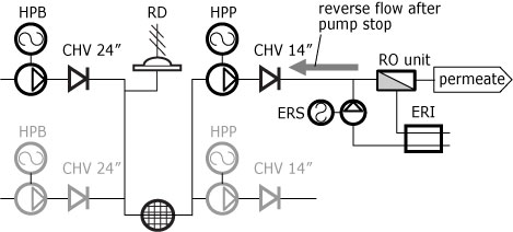
Figure 1 Tandem of 4 HPBs and 9 HPPs: ERI – energy recovery system
Solution
To answer this question we consider a special case - power failure - when all pumps are coasting to the full stop. We start from the case when the non-return valve after HPP is not installed.
Figure 2 shows the predicted performance of HPP linked to Pelton turbine (Palmachim plant, 2007, 3000 RPM). As seen after 4 seconds the HPP discharge pressure drops to the feed osmotic pressure. The said case may be used for qualitative transients analysis of the HPP equipped with ERI during power failure.
- As the stand-alone HPP has lower intertia than the tandem of HPP & Pelton turbine and no energy recuperation, the stoppage curve will be steeper. It may be assumed that the osmotic pressure be reached after 3 seconds.
- Upon the RO feed reaching the osmotic pressure, the permeate production drops to zero as well as the HPP delivery. So the RO membrane array may be modeled as the fast closing valve.
- Fast closing valve produces "plain" water hammer, its intensity is proportional to the piping length. In our case the length is below 150m, which corresponds to the water hammers of below 12 m.
- As the ERS pump speed is 1500 rpm, its coasting curve is more gradual than the one of HPP. It means that ERS + ERI system will continue pumping when the RO membrane production drops to zero. The reverse flow is formed, that propagates towards HPB.
- After the flow through HPP drops to zero, the non-return valve of HPB starts closing. The reverse flow accelerates this process terminating with loud slam sound of the water hammer.
- ERI stops and the process of the pressure equalization starts in the volume formed by the piping and RO membranes and hermetically sealed by the non-return valves and ERIs. The pressure decreases below osmotic one down to 15 - 28 Barg. The upper value may burst the GRP piping.
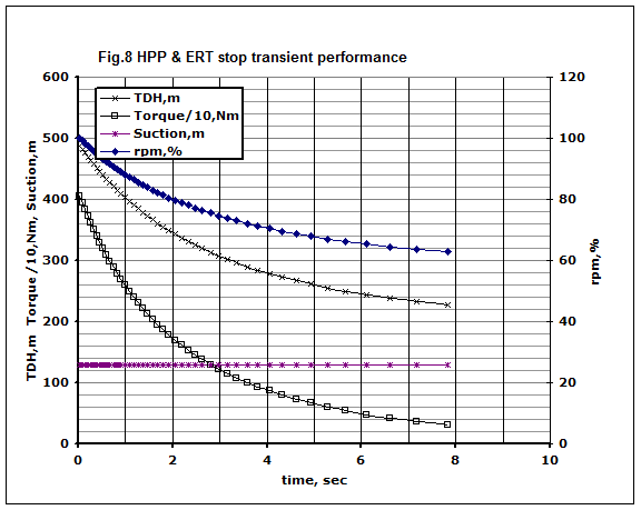
Figure 2 Transient performance of the HPP & Pelton turbine tandem after the power failure
(my white paper, 2006).
The water hammer produced by the non-return valve reverse flow is calculated by the formula [AWWA, 51].
h = av/g, where a- celerity, m/s; v - reverse velocity; g =9.81 1/s2
The reverse velocity depends upon the system deceleration and the non-return valve construction (Figure 3).
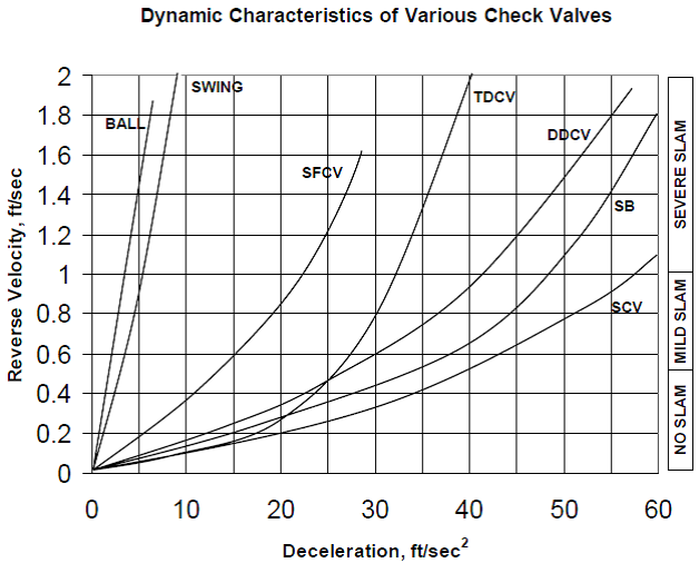
Figure 3 Dynamic characteristics of the non-return valves of 8 inch: DDCV - dual plate valve, SCV - linear stroke one (similar to NOREVA)
Deceleration is a ratio of initial fluid velocity to the deceleration time, which in our case is 3 seconds. The reverse flows for different valve sizes at deceleration of 1.2m/s2 sis given in Table 1.
| Valve size, inch | 8 | 14 | 24 |
| Reverse flow, m/s | 0.05 | 0.15 | 0.5 |
For fluid velocities of 3.5 - 4 meters the h value is below 50 m.
As the pressure surges caused by the water hammers (plain and reverse flow one) are relatively mild, one may conclude that the only dangerous situation to be handled is the pressure equalization after the water hammer.
This problem has relatively simple solution the 14" non-return valve at the HPP discharge. It catches the reverse flow water hammer and localizes the pressure equalization to the discharge segment of HPP. As this 14" valve closure is much faster (than that of 24"), the resultant of 2 reverse flows (in and out) is always negative. So the pressure buildup in the HPB discharge manifold will never happen and the rupture disc RD at the HPB discharge manifold is redundant.